Appendix B: F75111N DIO & Watchdog Device
The Arrakis Mk4 system provides optional DIO (Digital Input/Output) ports. This appendix explains the programming of these features, focusing on the Watchdog Timer under DOS.
Watchdog Timer Setup for DOS
You can access the necessary source and binary files here.
Source file:
F75111_Dos_Src.rarBinary file:
F75111_Dos_Bin.rar
Using the Demo Application
To use the Watchdog Timer demo application, follow these steps:
Boot the system into the MS-DOS operating system.
Locate and run the
75WDT.EXEbinary file.When prompted:
Input
1to enable the Watchdog Timer.Input
0to disable it.
Enter the desired countdown duration (in seconds) for the timer. When the countdown completes, the system will reset automatically.
Introduction
Using the Watchdog Timer Demo
WriteI2CByte(I2CADDR, CONFIG, 0x03);  // Set Watch Dog Timer function
WriteI2CByte(I2CADDR, WDT_TIMER, timer);  // Set Watch Dog Timer range (0-255)
WriteI2CByte(I2CADDR, WDT_TIMER_CTL, 0x73);  // Enable Watch Dog Timer in seconds and pulse mode
Alternatively:
WriteI2CByte(I2CADDR, WDT_TIMER_CTL, 0x00);
Pause Function Example
void pause(int time) {
    asm mov ah,0h; // Read system time counter
    asm int 1ah;
    asm add dx,time;
    asm mov bx,dx;
label:
    asm int 1ah;
    asm cmp bx,dx;
    asm jne label;
}
Watchdog Timer and DIO under Windows
You can access the necessary source and binary files here.
Source file:
F75111_DIOSrc.rarBinary file:
F75111_DemoBin.rar
How to Use the Demo Application
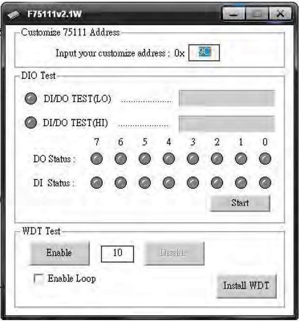
Using the Demo Application
Follow these steps to operate the DIO and Watchdog Timer (WDT) functions:
Test the DIO Function:
Press Start to begin testing the DIO functionality.
Enable the Watchdog Timer:
Press Enable to activate the Watchdog Timer (WDT).
Disable the Watchdog Timer:
Press Disable to deactivate the WDT.
Perform a WDT Loop Test:
Check the Enable Loop box, then press Enable to initiate a loop test for the WDT.
Configure Autorun for the Application:
Use Install WDT to set up the application to automatically run at system startup.
Press Install WDT again to remove the autorun configuration.
When the Watchdog Timer is active, the following icon will be displayed on the system:

Introduction
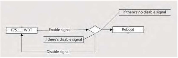
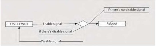
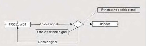
Watchdog Timer (WDT) Signal Handling
To enable the Watchdog Timer (WDT), use the following function:
F75111_SetWDTEnable(BYTE byteTimer);
// If no disable signal (F75111_SetWDTDisable()) is received before the timer countdown reaches 0, the system reboots.
Initial Port Address Configuration
The initial internal port address for the F75111 device is 0x9C.
Use this address to define GPIO pins for input/output operations and to enable the WDT function pin.
Setting Digital Output Value: Sample Code
void F75111::InterDigitalOutput(BYTE byteValue) {
    BYTE byteData = 0;
    byteData = (byteData & 0x01) ? byteValue + 0x01 : byteValue;
    // Additional bitmask adjustments can be applied here.
    this->Write_Byte(F75111_INTERNAL_ADDR, GPIO2X_OUTPUT_DATA, byteData);
}
Getting Digital Input Value: Sample Code
BYTE F75111::InterDigitalInput() {
    BYTE byteGPIO1X = 0, byteGPIO3X = 0, byteData = 0;
    this->Read_Byte(F75111_INTERNAL_ADDR, GPIO1X_INPUT_DATA, &byteGPIO1X);
    this->Read_Byte(F75111_INTERNAL_ADDR, GPIO3X_INPUT_DATA, &byteGPIO3X);
    // Adjustments to GPIO values can be made here before returning byteData.
    return byteData;
}
Enabling/Disabling WDT: Sample Code
Enable WDT
void F75111_SetWDTEnable(BYTE byteTimer) {
    WriteByte(F75111_INTERNAL_ADDR, WDT_TIMER_RANGE, byteTimer);
    WriteByte(F75111_INTERNAL_ADDR, WDT_CONFIGURATION, WDT_TIMEOUT_FLAG | WDT_ENABLE | WDT_PULSE | WDT_PSWIDTH_100MS);
}
Disable WDT
void F75111_SetWDTDisable() {
    WriteByte(F75111_INTERNAL_ADDR, WDT_CONFIGURATION, 0x00);
}
IO Device: F75111 in VB6 on Windows
You can access the necessary source and binary files here.
Source File:
75111_VB_v10.rarBinary File:
75111_VB_Src.rar
Using the Demo Application
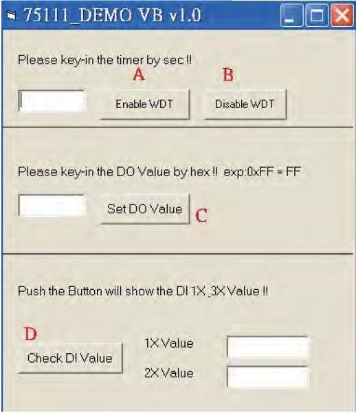
Enable the WDT Timer: Enter the countdown value (in seconds) in the left text box, then press Enable.
Disable the WDT Timer: Press the corresponding Disable button to stop the timer.
Set Digital Output (DO) Value: Input the desired hexadecimal value and press the corresponding button.
Check Digital Input (DI) Value: Press the button to display DI 1X & 2X values in the right text boxes.
Watchdog Timer and DIO in Linux
You can access the necessary source and binary files here.
Source File:
F75111v2.0L.tar.gzBinary File:
F75111v2.0LBin.tar.gz
Compiling the Source Code
Using Code::Blocks:
Install Code::Blocks using
apt-get install codeblocks.Open the existing project file (
F75111.cbp) and compile it.Add the following linker option:
pkg-config --libs gtk+-2.0 gthread-2.0
Navigate to Project -> Build Option -> Linker Settings -> Other Linker Options to set this.
Using Make:
cd F75111
make
./src/f75111  # Run the compiled binary
Using the Demo Application
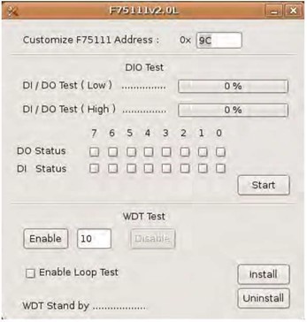
Start DIO Testing: Press Start to begin testing the DIO function.
Enable the WDT: Press Enable to activate the Watchdog Timer.
Disable the WDT: Press Disable to deactivate the Watchdog Timer.
Perform a WDT Loop Test: Check the Enable Loop box and press Enable to initiate loop testing.
Configure Autorun:
Use Install to set up the application to run automatically at system startup.
Use Uninstall to remove the autorun configuration.
When active, the system icon will blink: